


Roadside Safety - Barriers
Safety barriers are used to stop ‘out of control’ vehicles from:
- leaving the road and hitting roadside hazards, including slopes (roadside barriers)
- crossing into the path of on-coming vehicles (see median barriers).
They are designed to redirect the vehicle and have a lower severity than the roadside hazard they protect. There are several types of safety barrier (but within these types there are different systems which have their own specific performance characteristics).
Flexible barriers are made from wire rope supported between frangible posts. Flexible barriers may be the best option for minimizing injuries to vehicle occupants, however they may pose a risk to motorcyclists. These barriers deflect more than other barrier types and need to be repaired following impact to maintain their re-directive capability.
Semi-rigid barriers are usually made from steel beams or rails. These deflect less than flexible barriers and so they can be located closer to the hazard when space is limited. Depending on the impact these barriers may be able to redirect secondary impacts.
Rigid barriers are usually made of concrete and do not deflect. Rigid barriers should be used only where there is no room for deflection of a semi-rigid or flexible barrier. Rigid barriers are often utilized at high volume roadwork sites to protect road workers or other road users particularly where another barrier type is awaiting repair. Currently (depending on their height and other details) these provide the highest level of containment of heavy vehicles. In most cases following impact these barriers require little or no maintenance.
Vehicle parapets are rigid barriers in steel, concrete or a combination of both. They are installed onto highway structures such as bridges, retaining walls or building facilities. Their main purpose is to restrain an errant vehicle from falling off the structures.
Much of the benefit from the use of barriers comes from a reduction in crash severity. Although a crash may still occur, it is likely to have a safer consequence than colliding with the object that the barrier is protecting.
On existing roads retrofit of safety barriers can be challenging due to incompatibility between road layout, ground condition, roadside space, etc. and technical criteria for the installation of safety barriers. In these circumstances, solutions are often context-sensitive and may need to be tailored-made. Solutions for existing roads should be formulated with on-site surveys, comparison of options and risk assessments.
In dense urban areas where the roadside is needed for crossing, access to vehicles and loading or unloading activities, bollards may be a means to protect pedestrians from errant vehicles. However, rigid bollards may not be forgiving at high speed except for products designed to concurrently attenuate an impact.
Barrier end terminals
The need for end terminals arises from the deployment of safety barriers. Collision with untreated end terminals can result in lead to violent deceleration or penetration of the barrier into the compartment. On the other hand, a sloping barrier end can launch an errant vehicle into the air followed by rollover, falling off a drop or collision with rigid objects. All these scenarios have high potential for severe injuries to occupants of an errant vehicle.
End terminals of safety barriers should be addressed proactively on a route-wide basis.
The first step is to minimise the number of end terminals or relocate them to safer positions:
- Closing short gaps between two sections of the same safety barriers.
- Closing short gaps between two sections of different safety barriers with a transition.
- Extending the safety barrier upstream to locations with lower traffic speeds e.g. start of slip roads.
- Extending the safety barrier upstream of curves and other vulnerable sites.
The remaining sites should be addressed by the following measures:
- Extending and flaring the safety barrier to blend in with an upstream slope or anchor to an abutment wall.
- Adopting crash cushions or end terminals.
If these are not possible, the following treatments may be considered provided that traffic speed is low to moderate:
Flaring of beam barriers so that the end terminal is as far as practical from the general barrier alignment
Curved-out layout of rigid barriers or masonry parapets at a maximum angle of 40 degrees from the general barrier alignment
Sloping end of W-beam barriers of gentle gradient anchored into the ground may be an acceptable treatment. At low to moderate speed, an errant vehicle may ride over the barrier. There should not be major roadside hazards which can be reached by the errant vehicle.
Openings are sometimes needed along a safety barrier for emergency refuge, evacuation, operation or maintenance. These openings may be provided by an overlapping barrier layout such that the leading end terminal of the second barrier is shielded by the trailing section of the upstream barrier. However, this arrangement may not be suitable for undivided road where an errant vehicle may encroach onto the roadside from the opposite direction.
- If properly designed, installed and maintained, barriers should reduce the severity of crashes involving ‘out of control’ vehicles.
- When used in the median, safety barriers can greatly reduce the likelihood of head-on crashes.
- A safety barrier should only be built if the existing hazard cannot be removed (see Roadside Safety – Hazard Removal).
- On high volume, high speed divided roads and roads on steep sidelong ground, a continuous safety barrier can be a more appropriate strategy to address continuous downhill side slopes or a high density of hazardous objects.
- With the use of continuous barriers, adequate consideration should be given to refuge space for stranded vehicles and their occupants. In general, a shoulder width of 4m to 6m (3m minimum) in front of the barrier is desirable or else lay-bys should be provided at regular intervals. Access openings for emergency or maintenance may be provided with the safety barrier in overlapping layout.
- The end points (terminals or end treatments) of barriers can be dangerous if not properly designed, constructed and maintained (see Related Images for examples of poor terminal treatments).
- Safety barriers should be located so as to minimize high impact angles and should also allow space for vehicles to pull off the traffic lane.
- Safety barriers can have adverse implications on conspicuity and visibility at intersections, accesses, pedestrian crossings, etc. The problem is often aggravated around curves and crest profiles.
- Minor damage can reduce the safety benefits of barriers if they are not properly repaired.
- Roadside barriers are a hazard to motorcyclists.
- Ensure appropriate clearance behind safety barrier is considered particularly for flexible and semi-rigid barriers. With concrete barriers although they do not deflect, allowance must be made for any hazards taller than the barrier to be offset far enough from the face of the barrier so that during impact vehicles (particularly high vehicles such as trucks) do not lean over the barrier and strike the hazard
- If an uphill slope is not available, additional roadside area will need to be created to accommodate a flared barrier end terminal.
- If a flared safety barrier needs to cross a longitudinal ditch, appropriate detailing will be required to avoid an errant vehicle becoming snagged, under-riding or over-riding the barrier.
- If a high speed road or interchange is opened in stages, any stub ends should be properly treated.
The Star Rating Demonstrator is a freely available tool with the iRAP online software, ViDA. With the Star Rating Demonstrator, it is possible to explore the impact that this Safer Roads Treatment has on risk.
Treatment Summary
Costs | Medium |
Treatment life | 10 years - 20 years |
Potential casualty reduction | 40-60% |
Case Studies
Related Images
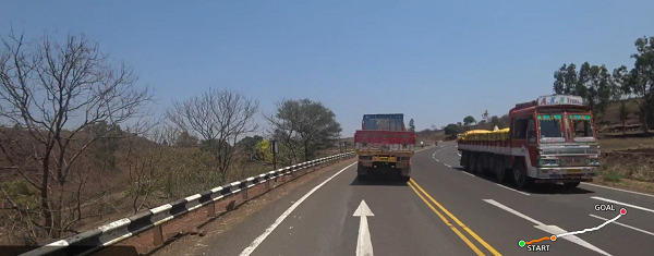 State highway in India with 2+1 lane configuration and roadside safety barrier. Image credit: iRAP
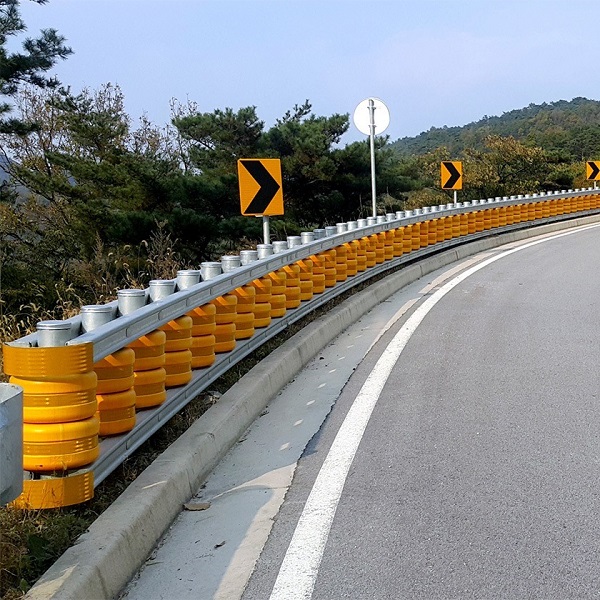 "Roller" safety barrier. Image credit: Unknown
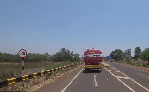 State highway with roadside safety barrier in India Image credit: iRAP
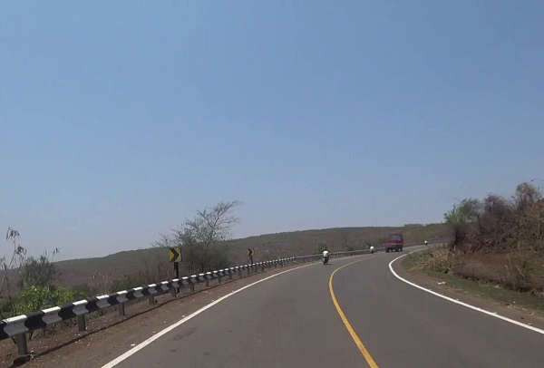 A curve with Chevron alignment markers and roadside barrier in India. This reduces the likelihood and severity of run-off crashes at curves. Image credit: iRAP
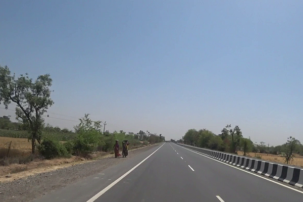 Dual carriageway state highway in India with concrete median barrier. Image credit: iRAP
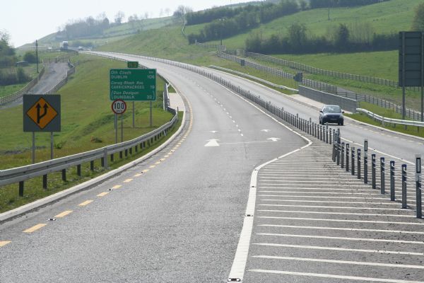 A divided road in Ireland with 2+1 lane configuration and wire-rope median barrier. Image credit: EuroRAP
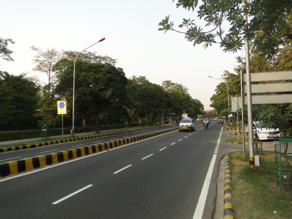 A divided urban road with narrow median in New Delhi, India. Image credit: Greg Smith
 A wire-rope median safety barrier in New Zealand. Image credit: New Zealand Transport Agency
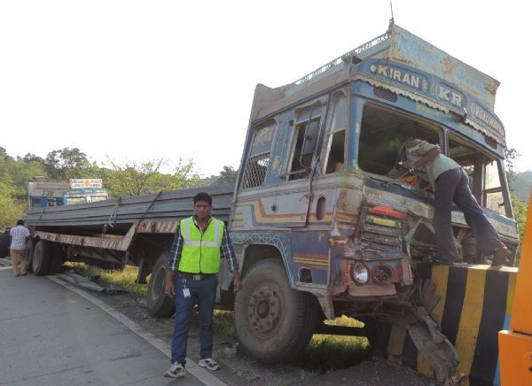 A run-off crash. Barrier end terminals must be designed to minimize risk upon impact. A crash attenuator would be a suitable end treatment in this case. Image credit: JP Research India
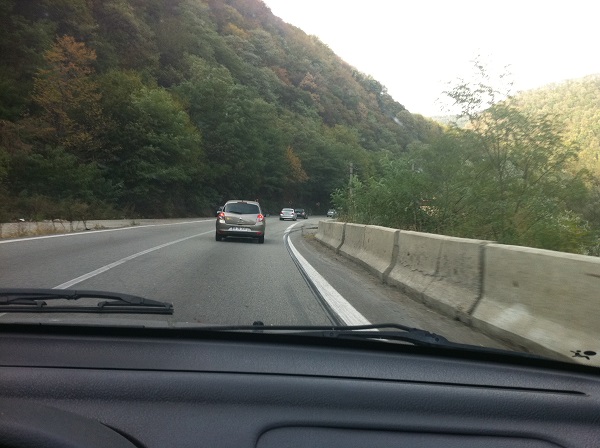 Concrete safety barrier with unconnected segments in Romania. Image credit: Alina Burlacu
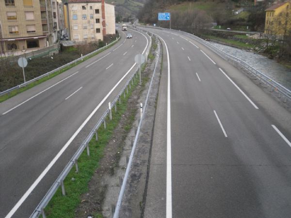 Duplication with median barrier in Asturias, Spain. Image credit: iRAP
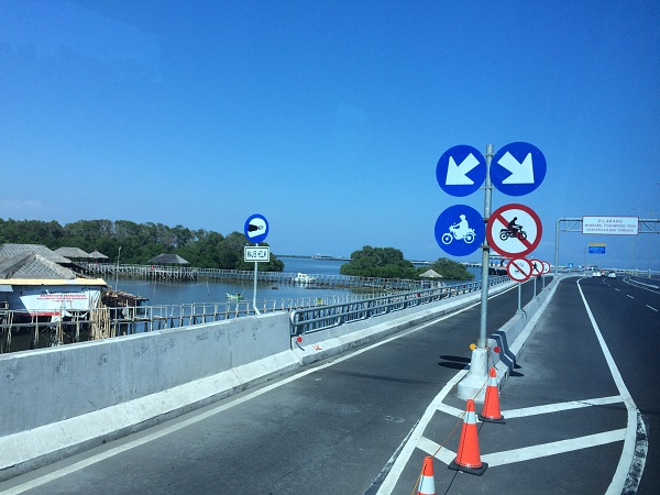 Exclusive motorcycle lane separated by concrete barrier. Image credit: Greg Smith
 Exclusive motorcycle lane separated by concrete barrier. Image credit: Greg Smith
 Concrete median barrier in France. Image credit: Unknown
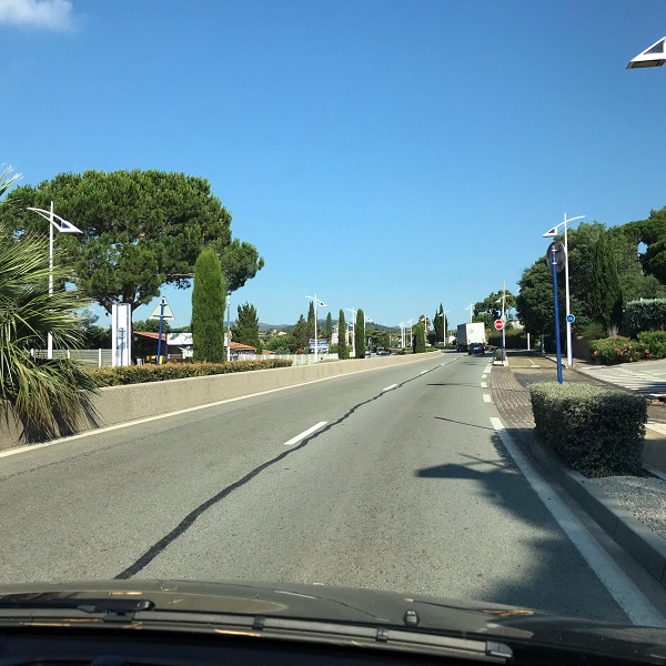 Media barrier in France. Image credit: Unknown
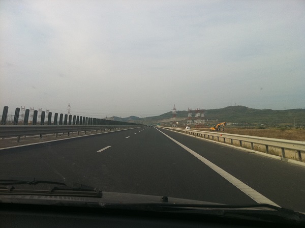 Motorway with safety barriers, wide shoulder and rumble strip edge lines in Romania. Image credit: Alina Burlacu
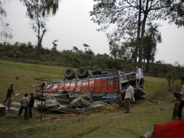 Overturned truck in Assam, India. Image credit: A. Tiwari
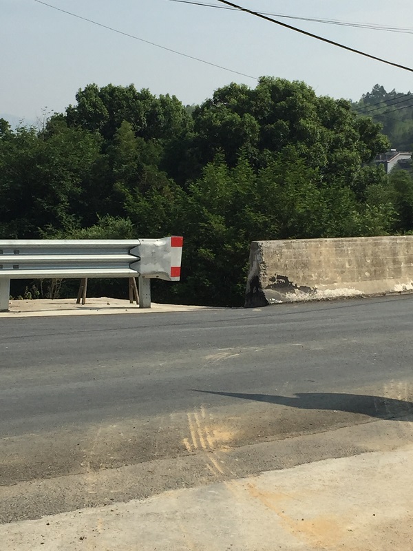 Poor connection between safety barrier and bridge parapet creates a roadside hazard, China. Image credit: Unknown
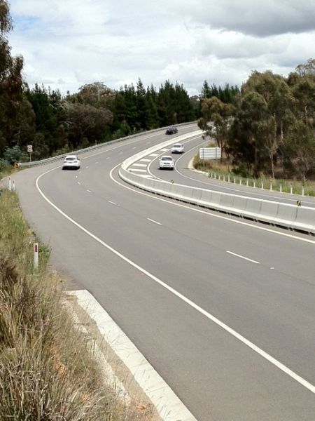 Roadside and median safety barriers on a curve in Australia. Image credit: Greg Smith
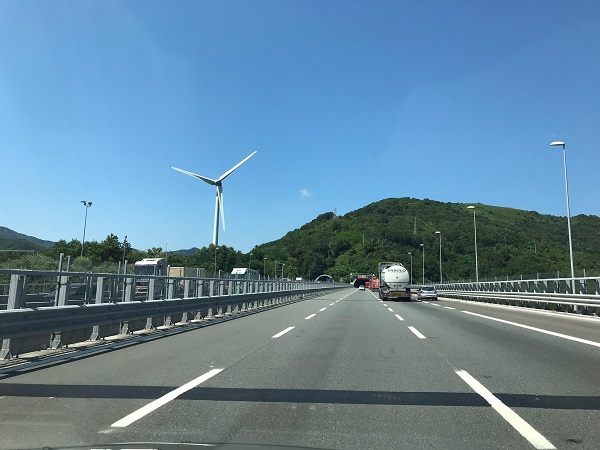 Roadside safety barriers in Switzerland. Image credit: Unknown
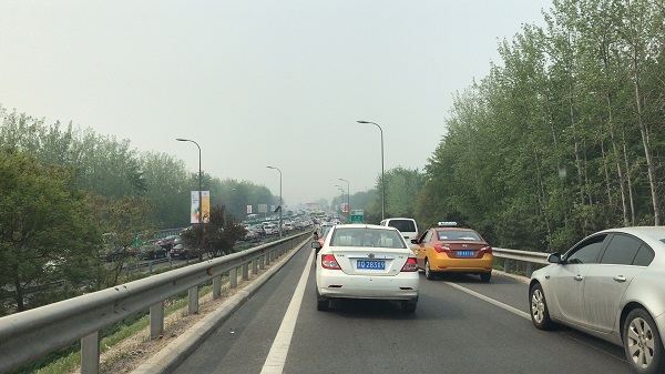 Roadside barrier - Beijing. Image credit: Unknown
 Roadside barrier at curve in Australia. Image credit: Unknown
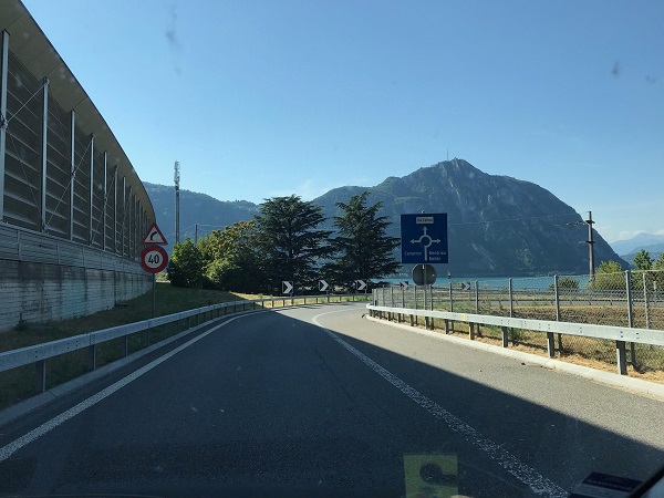 Roadside barrier at curve in Switzerland. Image credit: Unknown
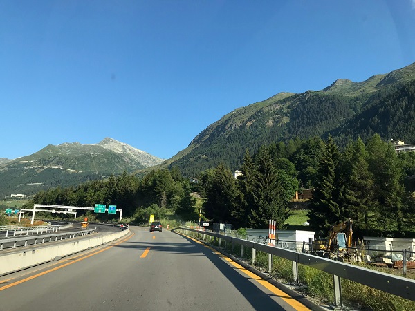 Safety barrier - Switzerland. Image credit: Unknown
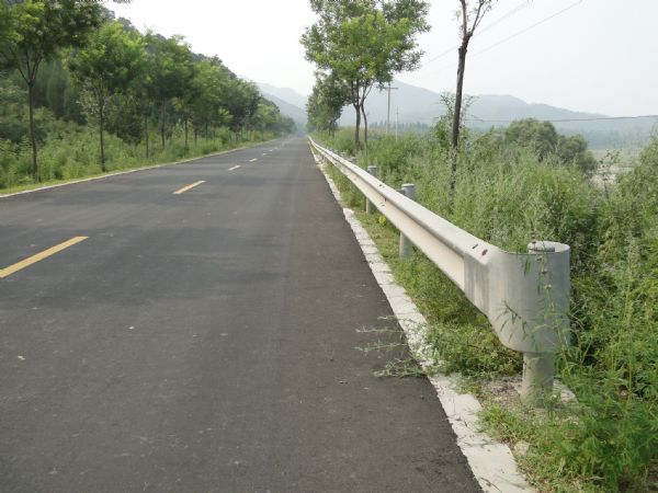 Unprotected safety barrier end in China. This type of end treatments pose high runoff risk. Image credit: Greg Smith
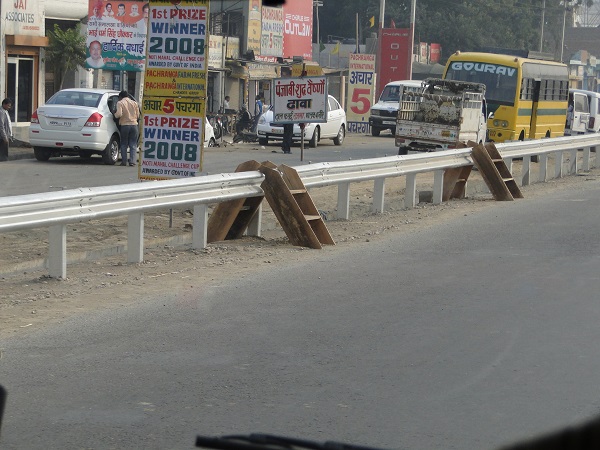 Safety barriers obstructing pedestrian desire line in India. Image credit: Greg Smith
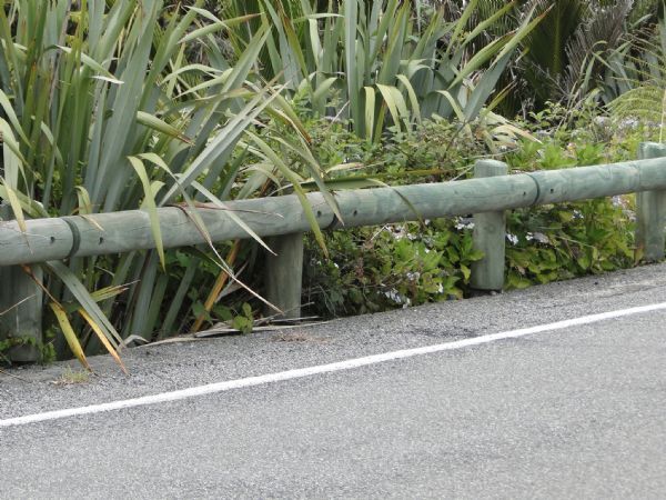 Steel-reinforced timber safety barrier in New Zealand, designed to blend in with the environment. Image credit: iRAP
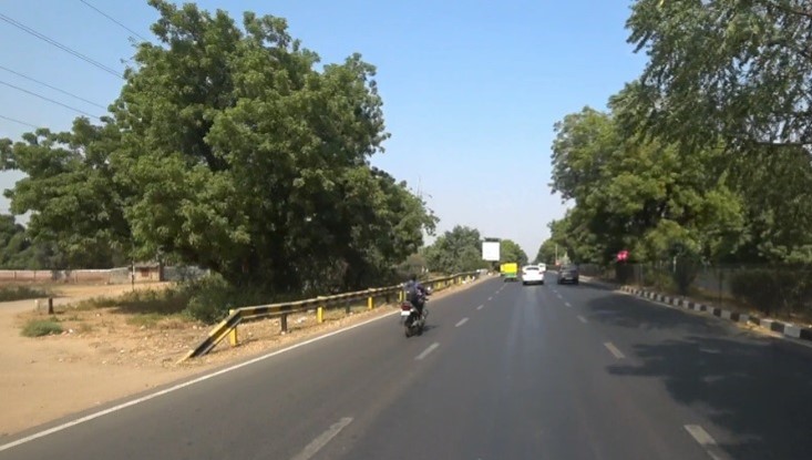 The end points of barriers can be dangerous if not properly designed. Slopped ground mounted crash barrier end presents a risk to vehicles that strike it. Image credit: iRAP


